Description
IEPE signal conditioner for precise measurements
IEPE is a technical and industry standard for sensor interface. The main characteristic of IEPE sensors is that they only require two wires. They are powered with the same wires that the return signal with information uses. Such sensors usually have integrated electronics and for interfacing them you need IEPE signal conditioner. That is the device that can supply power to the sensor as well as route the signal to the oscilloscope. The information (signal) from the sensor is then returned as voltage on the power line.
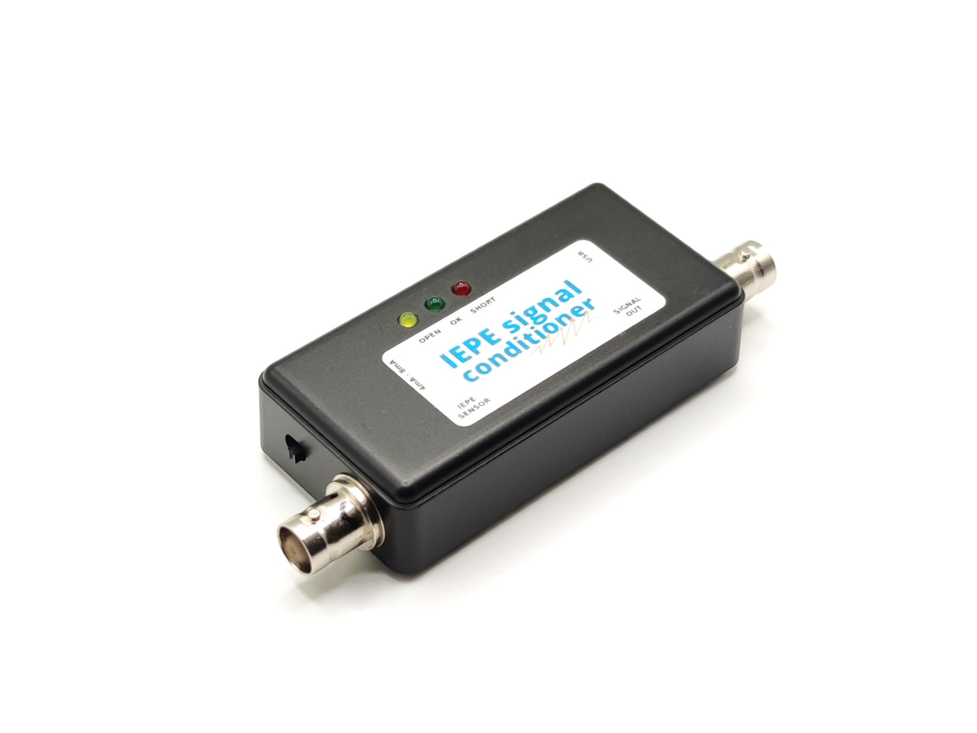
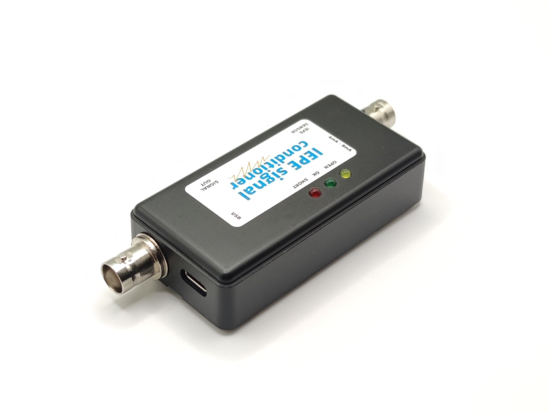
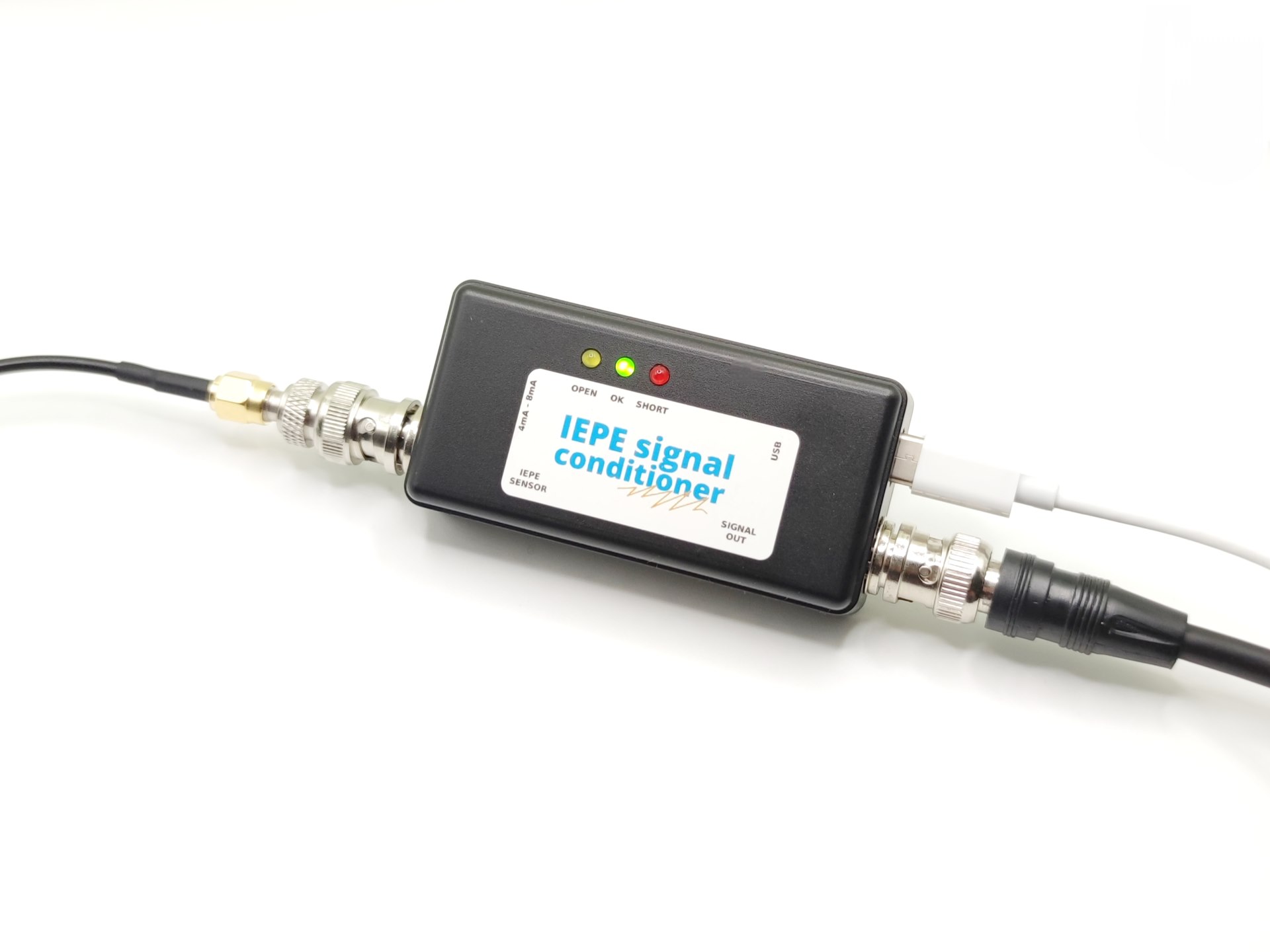
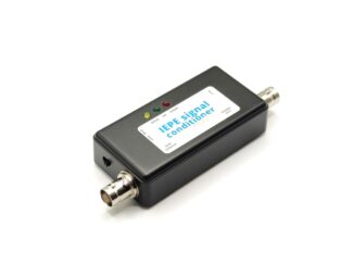
Our IEPE signal conditioner can detect the presence of the sensor and signals the sensor state with the LED. Yellow LED means that the IEPE conditioner is ready and sensor can be plugged in. When sensor is properly connected, green LED is on. In case of a short circuit or other malfunction the red LED is on. The sensor is connected with BNC connector on one side, and the other side is connected to the oscilloscope. For powering the conditioner USB-C is used with appropriate adapter. Note that the power supply for conditioner is 5V and not higher. The switch on the case is used for switching between 4mA and 8mA supply current for the IEPE sensor. That is used because higher current can provide better immunity to EMC radiation. Another benefit is the ability to use longer cables since capacity increases with the cable length.
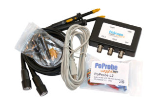
Our IEPE signal conditioner can be used with our USB oscilloscope PoScope.
Technical specification of IEPE conditioner
- 1Hz to 50kHz
- Gain 1:1
- LEDs that indicate the state of the sensor
- Standard BNC connector
- Selectable current range
- 4mA or 8mA current to the sensor
- Powered by standard USB-C

v.steinsland –
Works perfect!
Tested with IFM VSP001 (up to 12 kHz) IEPE industrial vibration sensor. The comparison of results gathered by Pico Tech TA487 is similar.